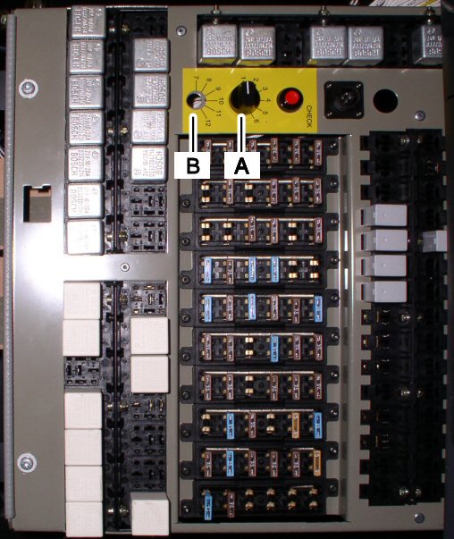
| To start the diagnostics, you must select the relevant system. According to design, one selector switch (A) or two selector switches (A and B) are built in for this purpose (on the main control panel). The assignment of the switch positions to systems is explained as follows (see also "Kombibus key" [325-90.00.001-01.0], main control panel). |
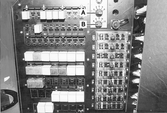 |
upper diagram: Switch configuration in the older design of control panel.
lower diagram: Switch configuration in the later design of control panel. |
 |
|
| Design with one selector switch |
|
| Switch position (switch A): |
1 = |
ABS/ASR |
| 2 = |
EDC/EFR |
| 3 = |
FMR |
| 4 = |
Gearbox |
| 5 = |
Retarder |
| 6 = |
Heating - ventilation - climate control |
|
| Design with two selector switches |
|
| Switch position (switch A): |
1 = |
ABS/ASR |
| 2 = |
EDC/EFR |
| 3 = |
FMR |
| 4 = |
Gearbox |
| 5 = |
Retarder |
| 6 = |
Additional to switch B |
|
| Switch position (switch B): |
7 = |
Heating - ventilation - climate control |
Note: |
To select systems 7 to 12 (switch B), switch A must always be in position 6. |
| 8 = |
Articulation angle control unit |
| 9 = |
ECAS |
| 10 = |
Driver's position (abbreviated in German to FAP) |
| 11...12 = |
not used |