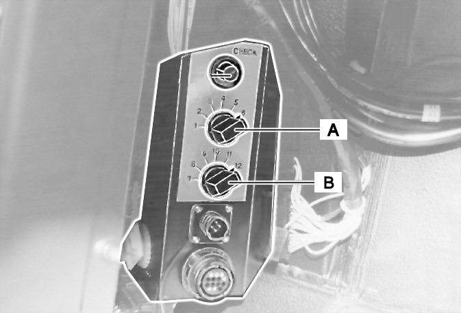
| To start the diagnostics, you must select the relevant system. According to design, one selector switch (A) or two selector switches (A and B) are built in for this purpose (on the main control panel). The assignment of switch positions to systems is explained as follows (see also the key to the wiring diagrams in the main control panel). |
 |
|
| Design with one selector switch |
|
| Switch position (switch A): |
1 = |
ABS/ASR |
| 2 = |
ADM |
| 3 = |
AVS/gearbox |
| 4 = |
Retarder |
| 5 = |
Kombi instrument |
| 6 = |
Heating - ventilation - climate control |
|
| Design with two selector switches |
|
| Switch position (switch A): |
1 = |
ABS/ASR |
| 2 = |
EDC |
| 3 = |
AVS/gearbox |
| 4 = |
Retarder |
| 5 = |
MFA/Kombi instrument |
| 6 = |
Additional to switch B |
|
| Switch position (switch B): |
7 = |
Heating - ventilation - climate control |
Note: |
To select systems 7 to 12 (switch B), switch A must always be in position 6. |
| 8 = |
ECAS |
| 9 = |
FMR |
| 10...12 = |
not used |