| |
|
| Read out fault memory |
|
| Prerequisites: |
|
- Vehicle at standstill
- Turn system selector switch to heating-ventilation-climate control (HLK) position (see electrical key)
- Drive switch on (drive switch to step 2, drive position)
|
|
| Fault output via display on control panel: |
|
- Hold down check key (red) for at least two seconds
|
|
| Note: |
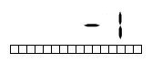
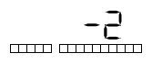
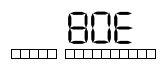
- The ATR system comprises the control panel for the passenger compartment and six or seven substations (seven only with Vario-Comp1). Each control unit has a separate fault memory. The alphanumeric position to the far right of the display shows which control unit has sent the indicated fault (addresses 1, 2, 3, 4, 5, 6, E or F).
Use the "+" key on the control panel to scroll through the individual fault memories.
Address assignment:
| Address |
Control equipment connector |
Control range |
| 1 |
1 A 32 |
Footwell area front, water valves, temperature sensors |
| 2 |
1 A 31 |
Footwell area rear (climate control system without Vario-Comp1), water valves, temperature sensors |
| 3 |
1 A 29 |
Ceiling left, water valves, temperature sensors and blower |
| 4 |
1 A 28 |
Ceiling right, water valves, temperature sensors and blower |
| 5 |
1 A 33 |
Climate control system (only with Vario-Comp1) |
| 6 |
1 A 30 |
Entrance 2, water valve, temperature sensor, tailgate damper blower (replacement substation) |
| E |
Driver's seat control panel |
Driver's seat/hot water supply |
| F |
Passenger compartment control panel |
Master computer |
|
|
1 electronic speed control for the coolant compressor |
|